Description
This article explains what a clean, expected EEG signal looks like in NIC's Liveview, the normal physiological artifacts you may see during a recording (chewing, eye movement), and the data-quality indicators that point to a hardware or setup problem, together with the correction for each. It is intended for operators reviewing live or recorded EEG signal quality on a Neuroelectrics device.
Materials / Devices / Software
Neuroelectrics device (8/20/32-channel EEG system) — the example screenshots in this article are from an Enobio 20 recording
NIC2 (Neuroelectrics Instrument Controller) software
Headcap with electrodes fitted, including the CMS and DRL reference electrodes
Electrode gel (e.g. Signagel) for gelled electrode setups
Pre-requisites
Device connected to NIC2 and a protocol loaded
EEG recording started (Liveview open and PLAY pressed) so channels are actively streaming
Step-by-step guide
1. Recognize a clean, expected EEG signal
A properly connected system shows continuous, low-amplitude oscillations on every channel, with no flat lines, sudden spikes, or slow drifting baselines.
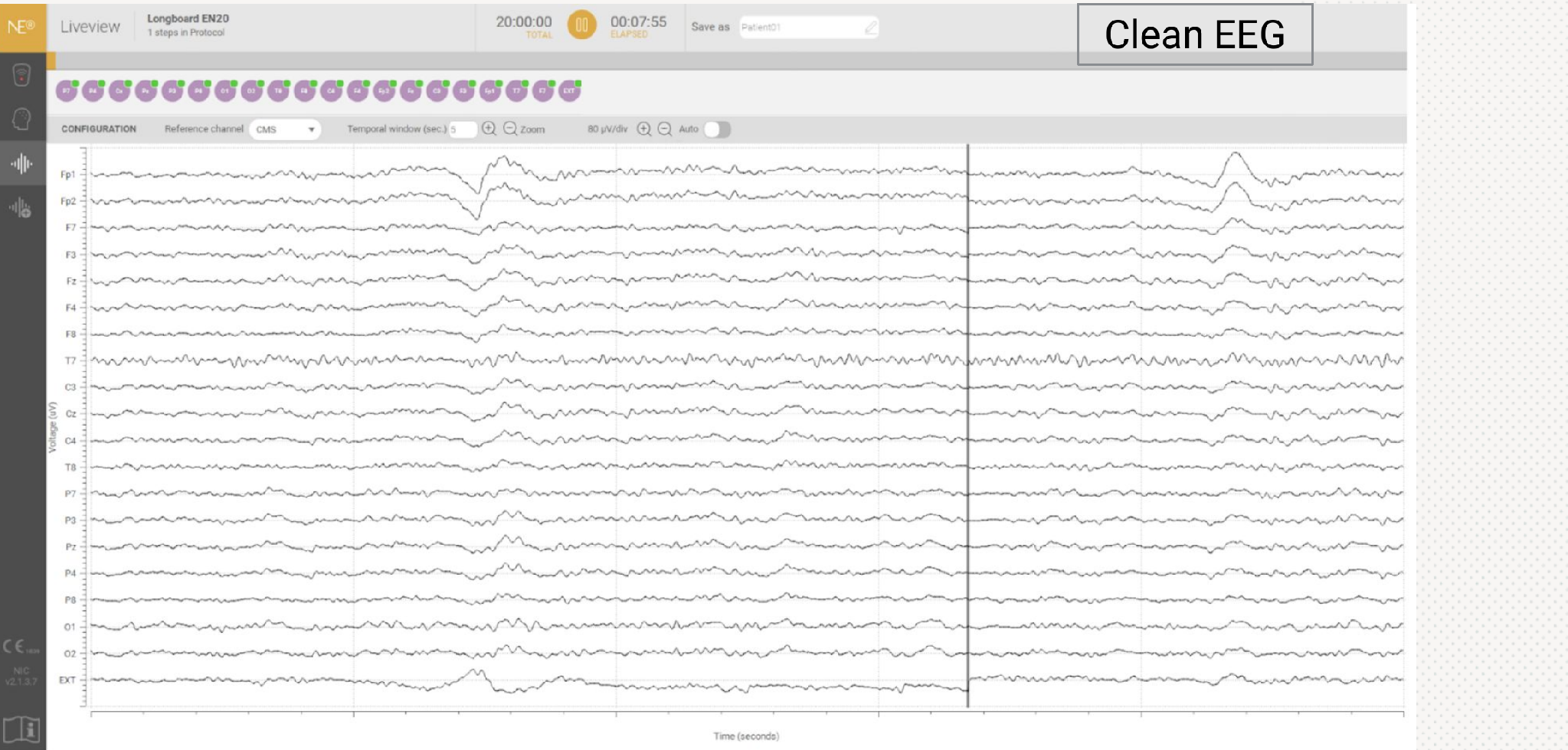
Example of a clean EEG signal in NIC Liveview (Enobio 20).
2. Rule out normal physiological artifacts
Some irregular-looking traces are expected and do not indicate a hardware problem — they come from the patient's own muscle or eye movements rather than the device or electrodes.
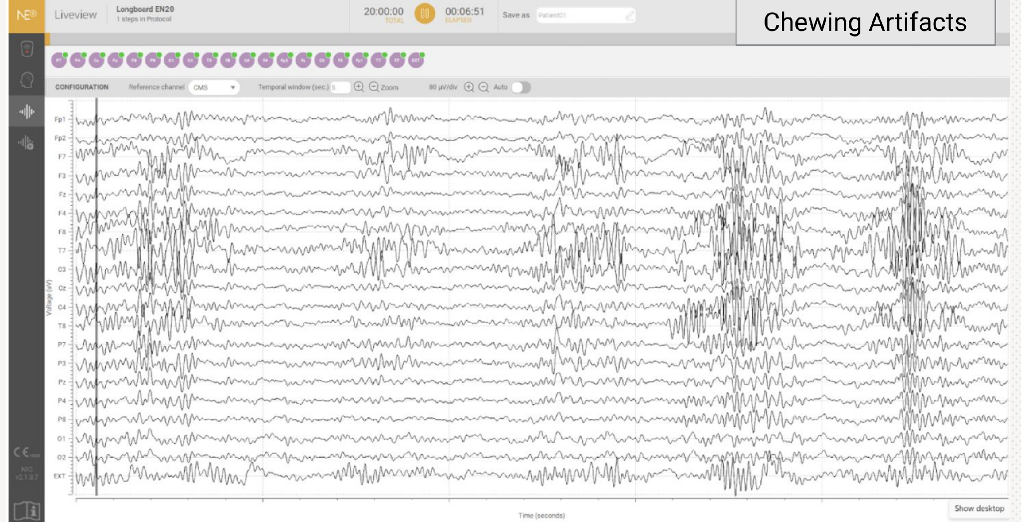
Chewing artifacts: high-amplitude, high-frequency bursts across most channels.
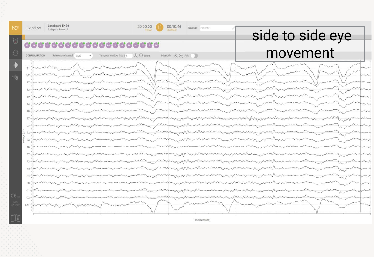
Side-to-side eye movement: slow deflections, most visible in the frontal (Fp1/Fp2) channels.
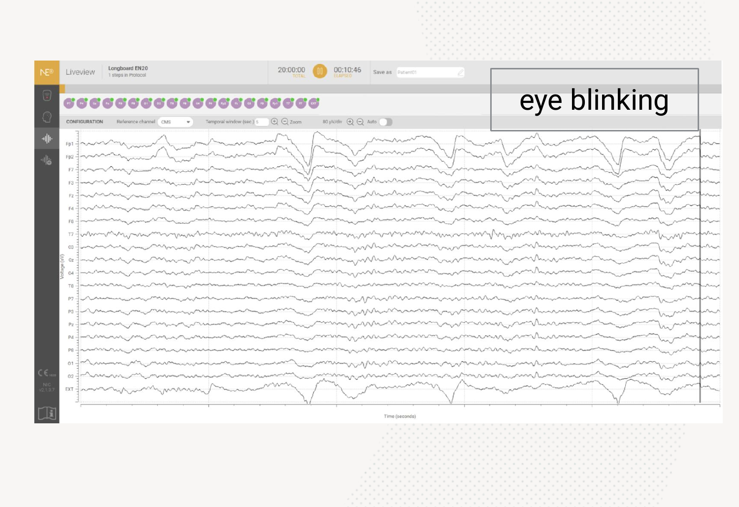
Eye blinking: sharp, repeated deflections in the frontal channels.
These patterns are physiological, not a connection or hardware issue, and do not require any correction.
3. Compare against the Common Problems if the signal looks abnormal
If a channel's trace doesn't match a clean signal or one of the physiological artifacts above, compare it against the data-quality indicators in the Common Problems section below to identify the likely cause and the correction to apply.
4. Confirm the signal is restored
After applying the correction that matches the indicator you identified, recheck the affected channel(s) in Liveview.
The channel(s) should show a continuous, artifact-free trace like the one in Step 1, with no flat lines, drift, or spikes.
If a connection issue is suspected, use NIC2's Impedance Check (or Recheck Impedance) to confirm the affected channel(s) return to an acceptable (green) value before resuming the recording.
Common Problems
EEG signal while CMS is not properly connected
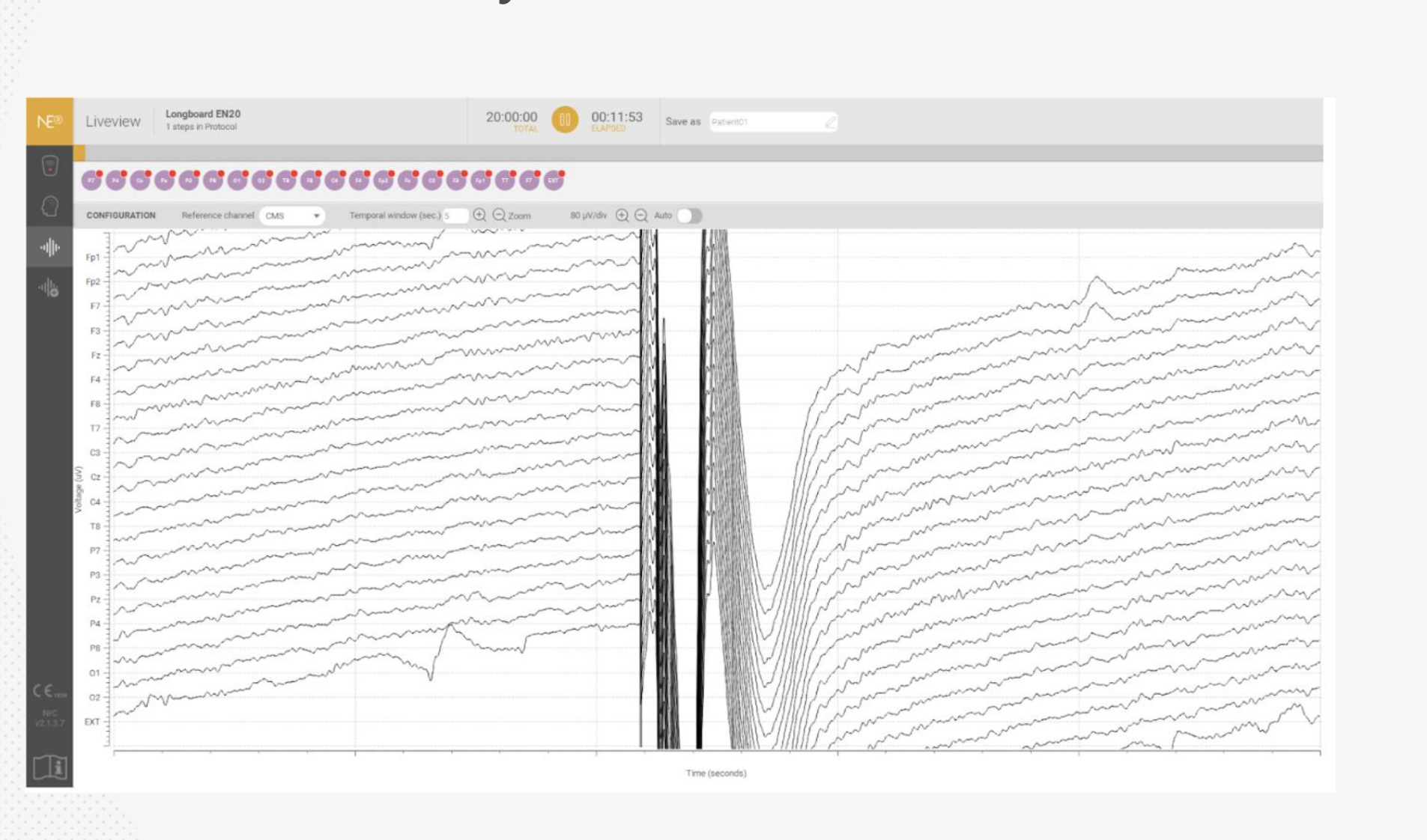
All EEG channels are referenced to CMS, so a poor CMS connection distorts the signal across every channel at once.
Correction: Check the CMS/DRL connection and the stick (Kendall) electrode placement. CMS/DRL should be positioned close to the cranial midline, or on the mastoid bones behind the ear.
If this does not improve data quality, consider replacing the mastoid electrodes.
EEG signal when CMS is completely disconnected
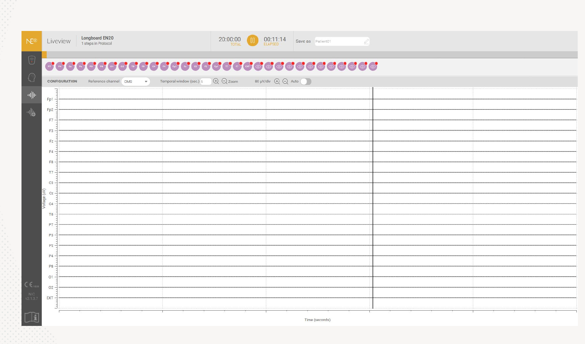
Correction: Connect the CMS cables to the stick electrode on the mastoid.
If this does not improve data quality, replace the mastoid electrodes.
If this still does not resolve it, consider replacing the cables or the device.
EEG signal with flat lines
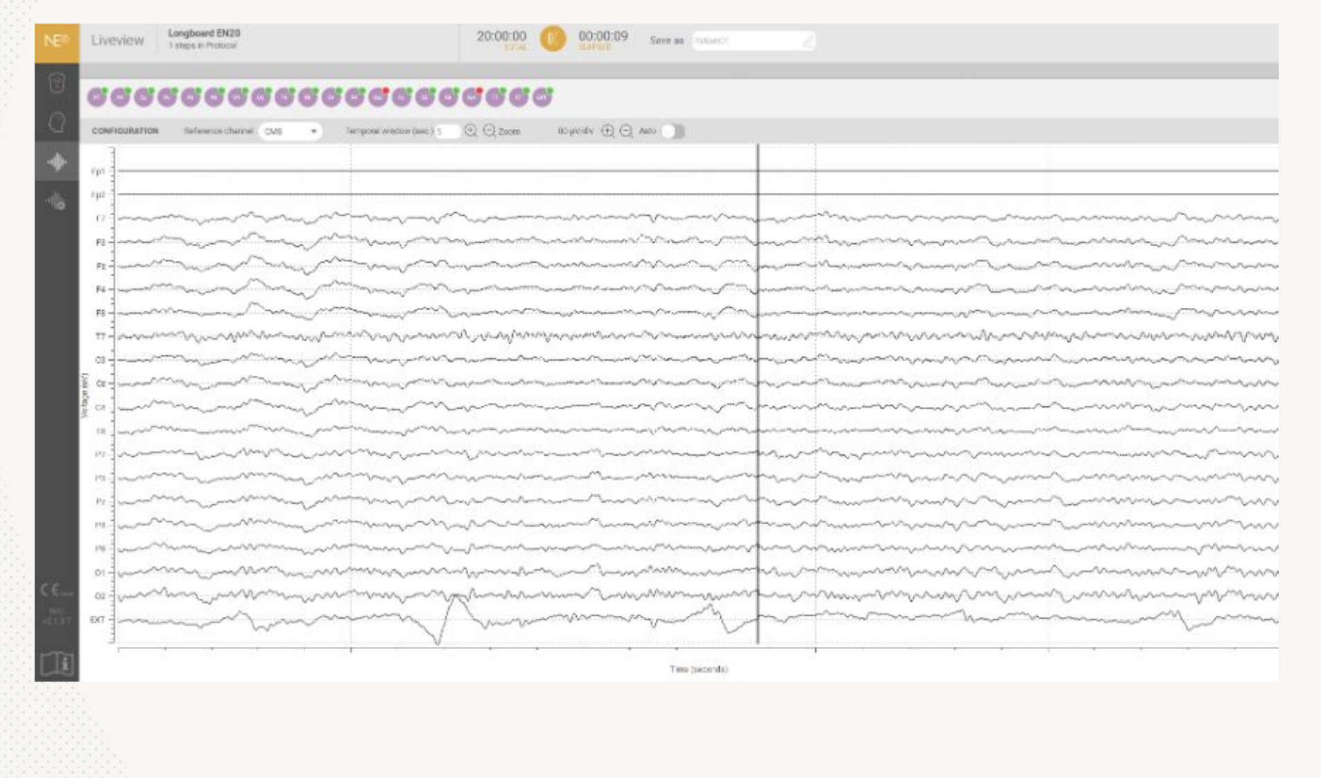
Caused by the absence of gel at the specific electrode position (Fp1 and Fp2 in the example shown).
Correction: Ensure the cables are correctly clipped onto the electrodes.
Add more gel on the channel(s) showing the flat line.
EEG signal with baseline drift in one channel
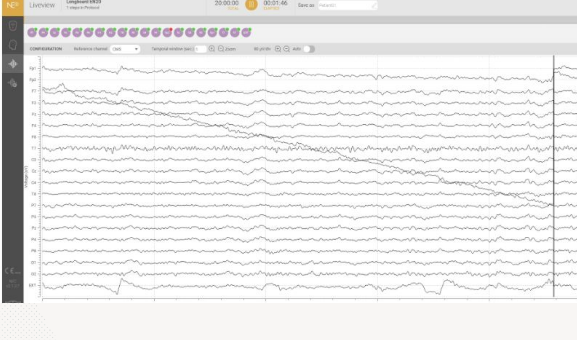
Caused by an insufficient amount of gel at the specific electrode position (Fp2 in the example shown).
Correction: Add more gel on the specific channel(s) showing drift.
EEG signal with baseline drift from a loosened electrode
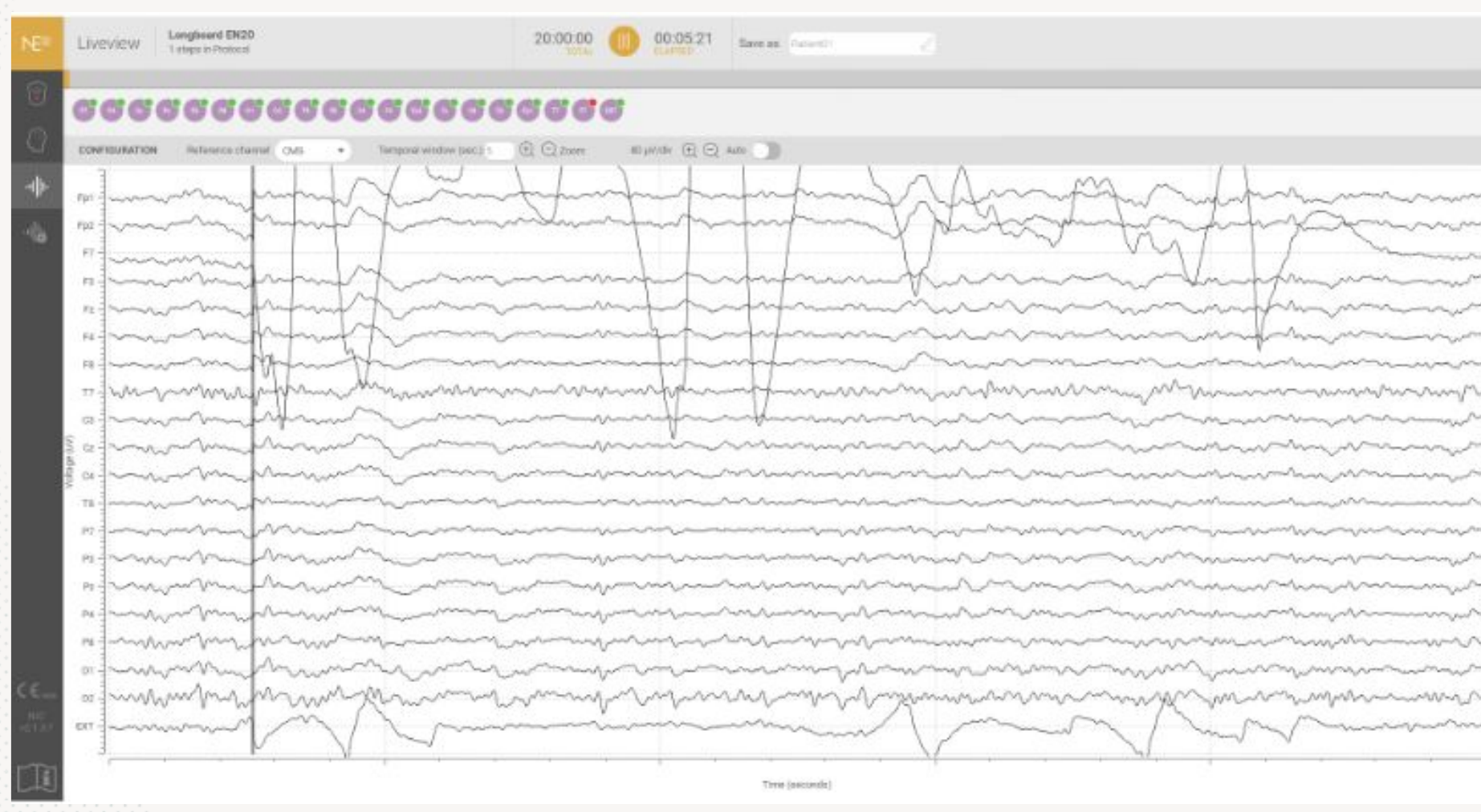
Occurs when one or more electrodes become slightly loosened, typically due to gentle head movement during the recording.
Appears as a slow, wave-like baseline shift. This can be challenging to identify, as it manifests gradually and may be mistaken for slow brain activity or another physiological signal.
Correction: Ensure all cable wires are properly clipped onto all electrodes and that the top part of the electrodes is properly screwed on.
EEG signal with electrode pop artifacts
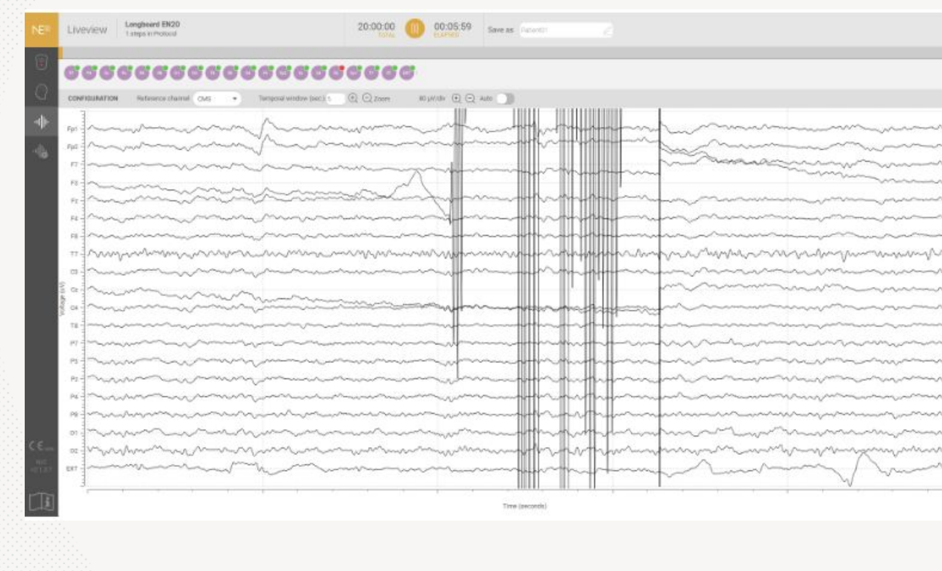
Caused by sudden disconnection of an electrode or cable; appears as sharp transients or spikes in the recording, isolated or in bursts.
Typically easy to identify due to the sudden onset and high amplitude.
Correction: Ensure all cables are properly connected to the electrodes as well as to the device.
Was this article helpful?
That’s Great!
Thank you for your feedback
Sorry! We couldn't be helpful
Thank you for your feedback
Feedback sent
We appreciate your effort and will try to fix the article