This article explains the Touchproof (DIN 42802-1) connector standard and how the Neuroelectrics Touchproof Adapter enables Enobio systems to work with third-party EEG electrodes and cables that use this connector type. It's intended for clinicians, researchers, and lab staff evaluating or setting up Enobio with non-Neuroelectrics electrode hardware.
Materials / Devices / Software
- Enobio 8, Enobio 20, Enobio 32 (and Enobio Dx 8/20/32)
- Touchproof Adapter 8, 20, or 32 (matched to your Enobio channel count)
- NIC2 or NIC-Enobio Dx software
- EEG electrodes built to the DIN 42802-1 standard
Prerequisites
NIC2 or NIC-Enobio Dx installed, with the Enobio system connected
A Protocol defined or selected in NIC matching the desired electrode layout
A stable surface near the subject to place the Necbox and Touchproof Adapter
What is the Touchproof standard (DIN 42802-1)?
"Touchproof" refers to the 1.5 mm DIN 42802-1 electrical connector standard, widely used across clinical environments for EEG electrodes and cables.
The design is intentional: touchproof connectors use recessed conductive pins or socket designs specifically to prevent users or patients from making direct physical or accidental electrical contact with live conductive surfaces during setup and signal acquisition. This is a safety-oriented connector design, not just a compatibility spec.
What the Neuroelectrics Touchproof Adapter does
The Touchproof Adapter is a passive accessory that sits between the Enobio acquisition unit (Necbox) and standard third-party EEG electrodes/cables built to the DIN 42802-1 standard.
- Function: Enables compatibility between Enobio and standard third-party EEG electrodes/cables using 1.5 mm DIN 42802-1 touchproof connectors.
- Passive design: Contains no active electronics, amplification, or signal processing — it is a conductive interface only.
- Signal path: Maintains a stable, low-noise conductive path between the electrode and the Enobio acquisition system.
- Configurations: Available in 8-, 20-, and 32-channel versions, matched to the corresponding Enobio system.
- Clinical workflow benefit: Lets facilities use touchproof electrodes already in clinical use, reducing setup time and avoiding session delays caused by proprietary-accessory unavailability.
Software Notes
Minor NIC2 and NIC-Enobio Dx updates accompany this change, aimed at usability and risk mitigation for the touchproof/third-party electrode use case — not new features:
Channel number and scalp position now display together in the LiveView panel (Enobio 8).
The setup guide now reminds the operator to connect CMS and DRL electrodes.
No firmware or mechanical changes to the Enobio device itself are required.
Compatibility
Enobio system | Matching Touchproof Adapter |
|---|---|
Enobio 8 / Enobio Dx 8 | Touchproof Adapter 8 |
Enobio 20 / Enobio Dx 20 | Touchproof Adapter 20 |
Enobio 32 / Enobio Dx 32 | Touchproof Adapter 32 |
Step-by-Step Setup Guide (Touchproof Adapter 32)
The procedure below is documented for the Touchproof Adapter 32 with Enobio Dx 32. The 8- and 20-channel adapters follow the same connection principles (module labeling, cable orientation, CMS/DRL reference leads).
1. Set up a stable work surface
Ensure a stable surface is available near the subject to place the Necbox and Touchproof Adapter.
2. Load the protocol in NIC
Launch NIC and load the Protocol
Use the Setup Guide in NIC to identify the required electrode positions.
3. Connect electrodes sequentially
Select a lead, place the electrode on the patient's head, and immediately plug the wire fully into the correctly labeled adapter port. Repeat until setup is complete.
Connecting sequentially (rather than all at once) prevents wire entanglement.
Ensure the physical placement on the headcap position matches the adapter's printed labels.
4. Connect the Touchproof cables to the modules
Connect the Touchproof cable(s) to the corresponding modules.
The Neuroelectrics logos must all face upward to ensure correct orientation.
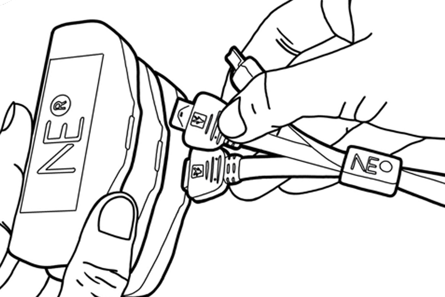
5. Connect the cables to the Necbox
Connect the free end of the Touchproof Cable(s) to the Necbox, using the Neuroelectrics logos as a guide.
8-channel: one 10-pin cable. 20-channel: one 10-pin and one 12-pin cable. 32-channel: one 10-pin and two 12-pin cables.
Always plug the 10-pin cable into the bottom Necbox slot; connect 12-pin cables to the middle and top slots as needed.
6. Connect the reference leads
Connect the CMS and DRL leads to their dedicated ports on the Touchproof Adapter, and attach them to the designated reference locations on the patient.
7. Position the hardware for acquisition
Place the Touchproof Adapter and the Necbox on a stable surface during EEG acquisition.
8. Run the session
Run the session.
9. Confirm the connection with an impedance check
Use Impedance Check to confirm that adequate electrical continuity has been established between the electrodes and the scalp.
Resolution evidence: all connected channels show acceptable impedance under the threshold configured in NIC.
Common Problems
Incorrect connection of a Touchproof cable or an electrode lead will result in high impedances.
If high impedances persist after re-verifying all connector connections, consult the setup guide.
Was this article helpful?
That’s Great!
Thank you for your feedback
Sorry! We couldn't be helpful
Thank you for your feedback
Feedback sent
We appreciate your effort and will try to fix the article